WIR TX75 S
Slave emitter for WIR TX75Product Highlights
- 5-year warranty
Description
The WIR TX75 S infrared slave emitter can be added to the WIR TX75 C/D mid-range infrared transmitter(s) for additional coverage of up to 24,000 square feet*, when mounted up to 100 feet from the master emitter. A maximum of two slaves can be added for up to 36,000 square feet total coverage. Placing additional slaves in the same room increases coverage and enhances freedom of movement. A single CAT5 cable carries both power and signal from the WIR TX75 C/D to the slaves – truly a one-cable connection. Linking bar and mounting bracket are included. 5-year warranty.
Use for:
- Courtrooms
- Conferences
- Houses of Worship
- Universities
- Cinemas
*Operating range varies based on receiver used. See emitter specifications for coverage area by receiver type.
System Includes
(1) WIR TX 75 S infrared slave emitter
(1) WCA 096 12" CAT5 cable
(1) WCA 091 25’ CAT5 cable
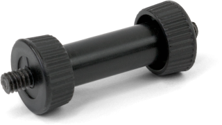
(1) MLB 003 slave linking bar
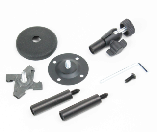
(1) BKT 024 wall/ceiling mounting bracket

|

|

|
Features
- Add one slave unit to the WIR TX75 C/D mid-range infrared transmitter for additional coverage of up to 24,000 square feet. Add two slaves for coverage of up to 36,000 sq. ft.
- Truly a one-cable connection- a single CAT5 cable carries both power and signal from the WIR TX75 C/D to the slaves
- 5-year warranty
Specifications
WIR TX75 S Architectural and Engineering Specifications
- The infrared slave emitter will work with the WIR TX 75 C (or D) infrared transmitter(s).
- The slave emitter shall have a minimum coverage of 6,000 sq. ft. with the WIR RX22-4 receiver in single-channel mode.
- The slave emitter shall be housed in a heavy-duty black plastic enclosure with a durable infra-red transparent front lens. It shall be convection cooled without fans. It shall have the ability for mounting on an omni-directional mounting bracket or a linking bar to mount above or below the WIR TX 75 C (or D) transmitter. It shall have a removable front bezel.
- The slave emitter shall have a single CAT-5 input which shall deliver both power and baseband signal from the WIR TX 75 C (or D) transmitter. It shall have a green LED indicator showing when power is received from the WIR TX 75 C (or D) transmitter and a yellow LED showing audio is being received from the WIR TX 75 C (or D).
- There shall be a switch on the back to turn off the indicator LED’s if desired.
- The slave emitter shall be covered by a five-year warranty, 90 days on accessories.
- This infrared slave emitter shall be the Williams Sound model WIR TX 75 S.
WIR TX75 S
|
Dimensions, Weight: |
10.0" W (25.4 cm) x 3.1" D (7.9 cm) x 1.5" H (3.8 cm) w/o faceplate or 2.5" H (6.4 cm) w/faceplate, 0.6 lbs (0.3kg) |
|
Color: |
Black with silver colored silk screen and silver colored faceplate Optional: white colored faceplate |
|
Sleep/Power Save Mode: |
Shuts off carrier when no audio is present for 3 minutes |
|
Modulation: |
FM Wideband, ±50kHz deviation max, 50 μS pre-emphasis |
|
Carrier Frequencies: |
2.3MHz (Ch1) and 2.8MHz (Ch2). Default at power on = carriers off. Carriers are automatically enabled upon presence of audio. |
|
Emitter IR Power: |
0.7 W |
|
Slave Coverage Area |
Note: Slave emitter cannot be used without a master transmitter, but if the slave emitter is aimed so that its coverage area does not overlap that of the master, on its own it will provide: 12,000 sq. ft. (464 sq. m.) in single-channel mode with the RX22-4 receiver 6,000 sq. ft. (557 sq. m.) in single-channel mode with the RX15-2 receiver 4,000 sq. ft. (186 sq. m.) in single-channel mode with the RX18 receiver |
|
Master + Slave Coverage Area (minimum, 1-ch mode) |
If slave transmitters are aimed to maximize coverage area (so that their coverage areas minimally overlap that of the master): 24,000 sq. ft. (2,230 sq. m) in single channel mode with the RX22-4, a master and (1) slave transmitter 36,000 sq. ft. (3,345 sq. m) in single channel mode with the RX22-4, a master and (2) slave transmitters |
|
Indicators On/Off: |
2-position switch turns on/off indicator lights |
|
Signal-to-Noise Ratio: |
70 dB, (line input) |
|
Frequency Response: |
95Hz to 17.6kHz, -3dB re 1kHz (line input) 125Hz to 17.0kHz, -3dB re 1kHz (microphone input) |
|
Total Harmonic Distortion: |
<1% (1 kHz, nominal deviation, line or microphone input) |
|
From Master Input |
8p8c RJ45 connector input provides 48VDC 0.4A power, baseband RF, and a bi-directional RS-485 bus for control and status communications. |
|
Slave Extension Cable: |
CAT-5e (or better) cable, maximum 100’ length, with RJ-45 8P8C male connector on each end, TIA568B |
|
Slave Status Indicators |
Green: Power/Unit Status Yellow: Transmit/Cable Status |
|
Operating Requirements: |
0-50° C (32°-122°F) |
|
Mounting Kit: |
Wall or Ceiling mount: BKT 024 Omnidirectional mount Optional: slave linking bar (MLB 003) |
|
Warranty: |
5 Years |
|
Approvals: |
CE, C-tick, FCC, Industry Canada, WEEE, RoHS, CB Scheme |
|
Compatible Receivers: |
WIR RX22-4, WIR RX18, WIR RX15-2 |
Other Models
WIR TX75 C, WIR TX75 D
Accessories for Slave emitter for WIR TX75
downloads
| Download/View | Name | Type | Language |
|---|---|---|---|
|
|
WIR TX75 C/D Quick Setup Guide | Manuals | English |
|
|
WIR TX75-S Specifications | Specifications | English |
|
|
WIR TX75-S Quick Setup Guide | Manuals | English |
|
|
WIR TX75 C/D Manual | Manuals | English |
Videos
| Name | Description | Duration |
|---|---|---|
| Williams Sound: WIR TX75 Preview | Preview of the Williams Sound WIR TX75 |
2:52 |


